Device: MacBook Pro 14" 2023, A2779 (M2 Pro / M2 Max)
Board: 820-02841
Symptom: dead on arrival. No chime, no screen, and the USB-C charger never goes above 5 V.
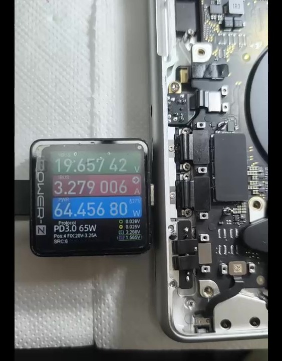
Result: after replacing one speaker amplifier (and its bootstrap capacitor), the charger negotiates 20 V (the Mac pulls 64.5 W) and the Mac boots. The right speaker distorted the next day, but that turned out to be the speaker module, not the new amp. The scope proof is in Step 6.
Step 1 – why “stuck at 5 V” means a main-rail problem
A USB-C charger always starts at 5 V. The Mac only asks for 20 V once its main power rail, PPBUS, is healthy. With PPBUS pulled down by a short, it never gets that far, so a USB-C meter shows 5 V and a few hundred mA, forever.
So “stuck at 5 V” is not a charger or port fault until you’ve checked PPBUS for a short to ground. Here it was shorted:
- PPBUS to ground, diode mode (red probe on ground): 0.080 V. That’s practically zero, a dead short.
Step 2 – finding the part
Many loads hang directly on PPBUS, so the short can be anywhere along it. On this board it was UR700.
How it was found: inject a low voltage into PPBUS from a bench supply (current-limited, below the rail’s normal voltage) and watch the board with a thermal camera. UR700 was the part that heated up.
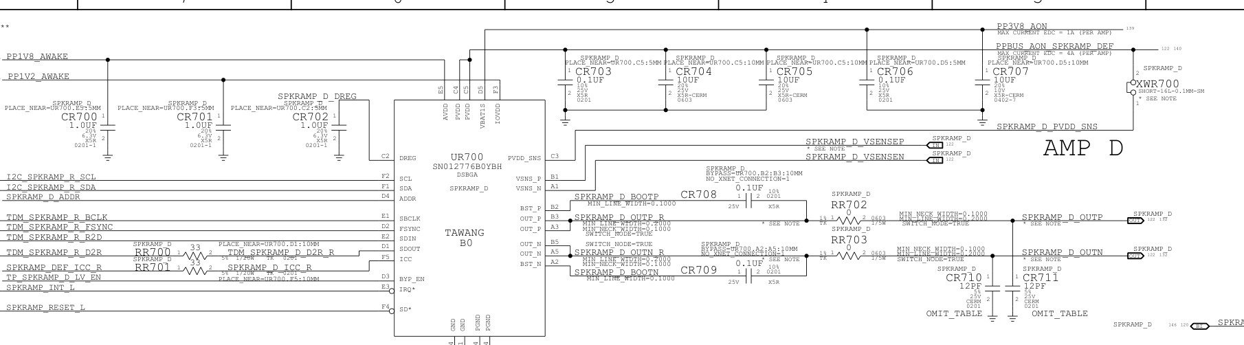
UR700 = speaker amplifier “AMP D” (part SN012776B0YBH, a small 30-ball BGA). Look at its supply in the schematic:
- Its power pins (PVDD, C4/C5) sit on PPBUS_AON_SPKRAMP_DEF.
- That rail is PPBUS itself, only joined through a short link XWR700: the label says “max current 4 A (per amp)”.
- Amps D, E and F (UR700 / UR730 / UR760) all share it.
A speaker amp shorted inside = a dead short on PPBUS = the whole Mac dead at 5 V.
Step 3 – remove the amp
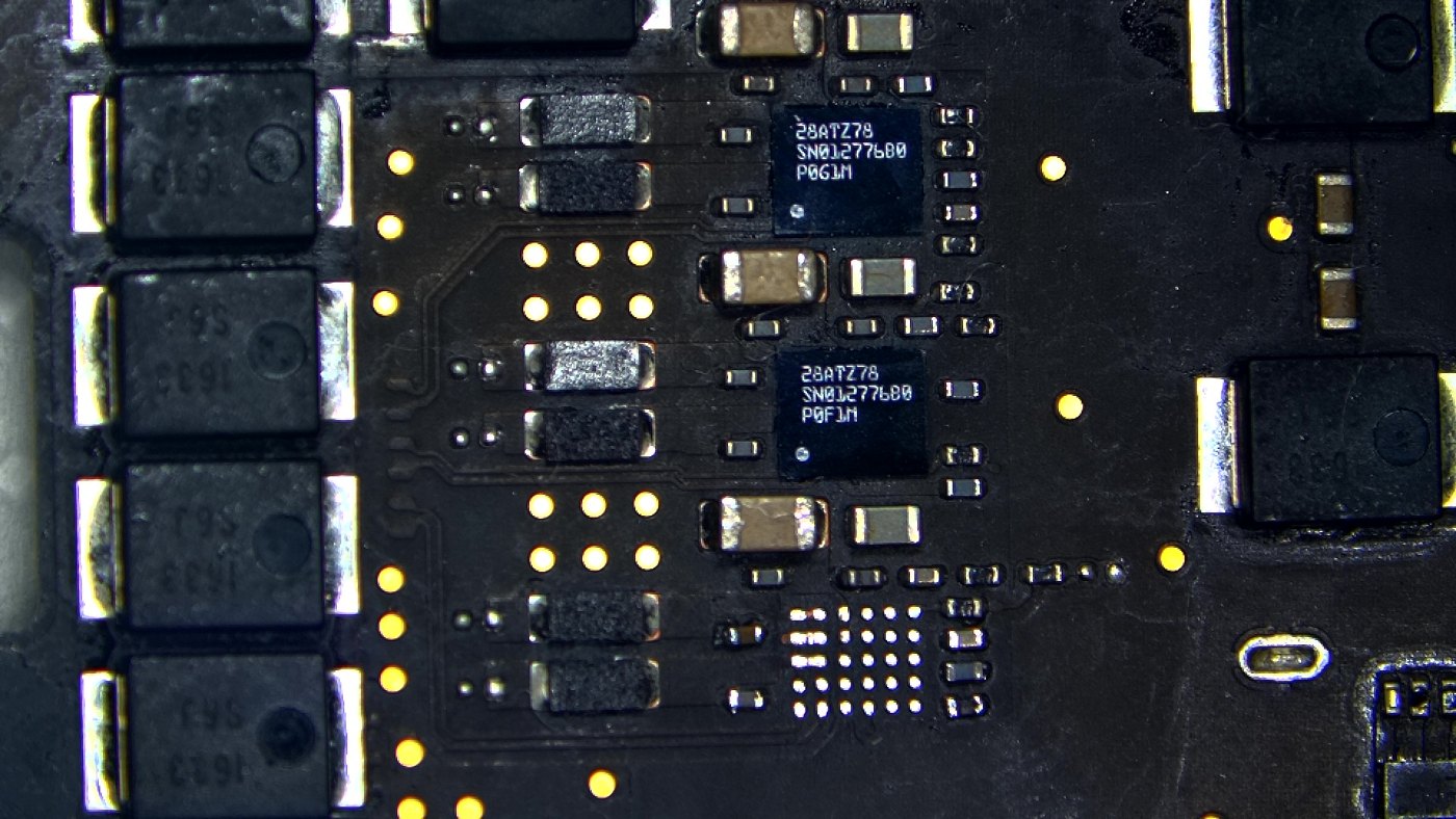
With UR700 off, the PPBUS short is gone. The Mac can even run without one speaker amp, so this is a good moment to test power-up before fitting the new chip. Only the speaker driven by AMP D stays silent.
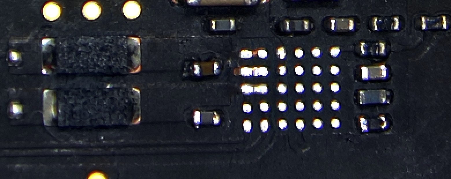
Tip for the empty site: the three double-size pads in one corner are the amp’s output and ground pins. They’re double by design, not bridged. On this board a little copper showed next to two of them where the solder mask had lifted, so keep that area clean and flat before the new chip goes down.
Step 4 – the capacitor that “read zero”
Before the amp came off, CR708 read 0 in diode mode. It looks like a second shorted part. It isn’t:
- CR708 = 0.1 µF, 25 V, 0201 – the amp’s bootstrap capacitor, between BOOTP (UR700 pin B2) and the amp’s output OUTP.
- The BOOTP side connects to nothing but CR708 and the amp. So the 0 was the dead amp, measured through the capacitor.
- With UR700 removed, CR708 read OL (open), which is what a healthy capacitor reads.
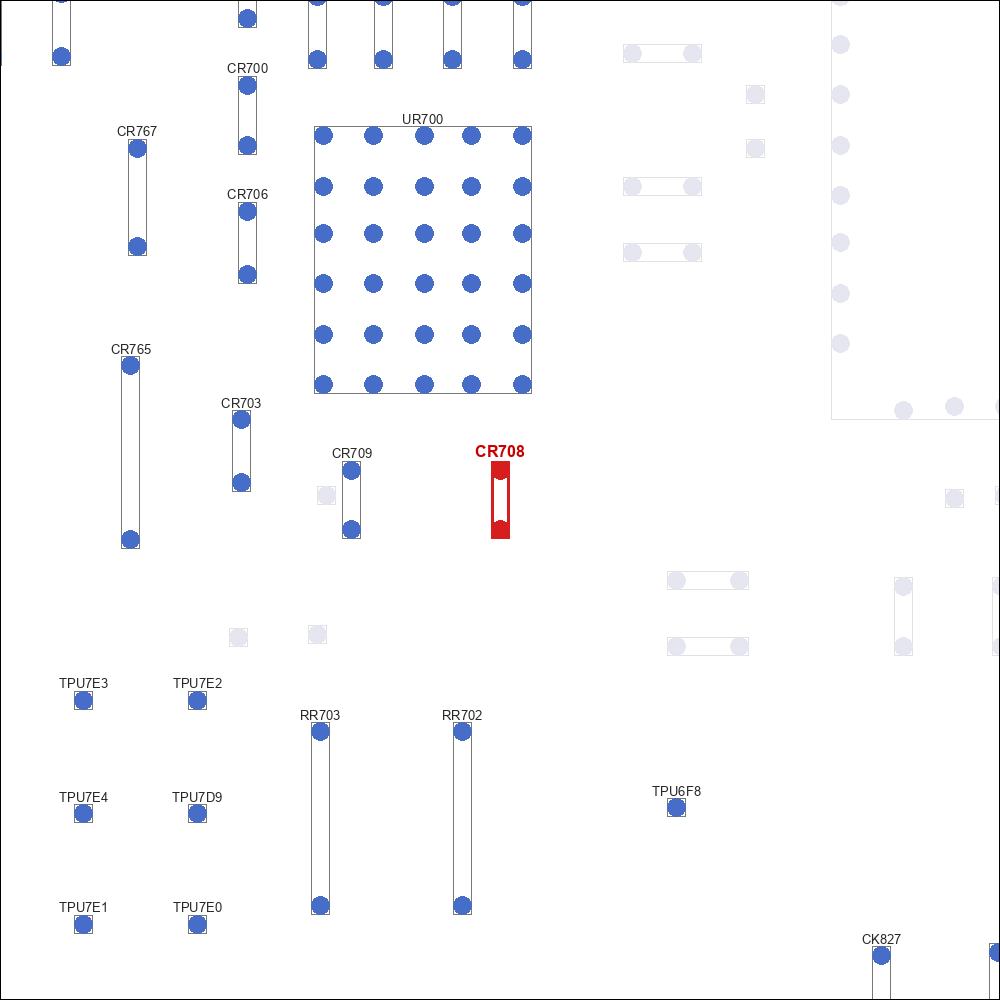
We replaced CR708 anyway, since it sat right on the failed chip.
If you replace the bootstrap capacitor, match the voltage, not only the value. It only holds about 5 V, but tiny 0201 capacitors lose much of their capacitance under voltage. A 6.3 V part can end up far below 0.1 µF in use, while a 25 V part keeps most of it. 0.1 µF 0201 parts rated 6.3 V are everywhere on donor boards. Don’t use those. Ours came from a donor board, checked against its schematic: 0.1 µF, 10 %, 25 V.
Step 5 – new amp, measure, power up
- A brand-new UR700, same part number SN012776B0YBH. Don’t swap in a different SN0127xx number. Its marking (29AV0P8) is a newer batch than the two original amps beside it (28ATZ78), and it comes with 30 fresh balls, so no reballing is needed.
- CR708: the 0.1 µF 25 V capacitor from the donor board.
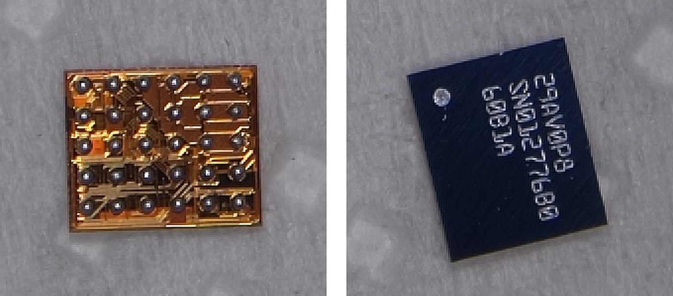
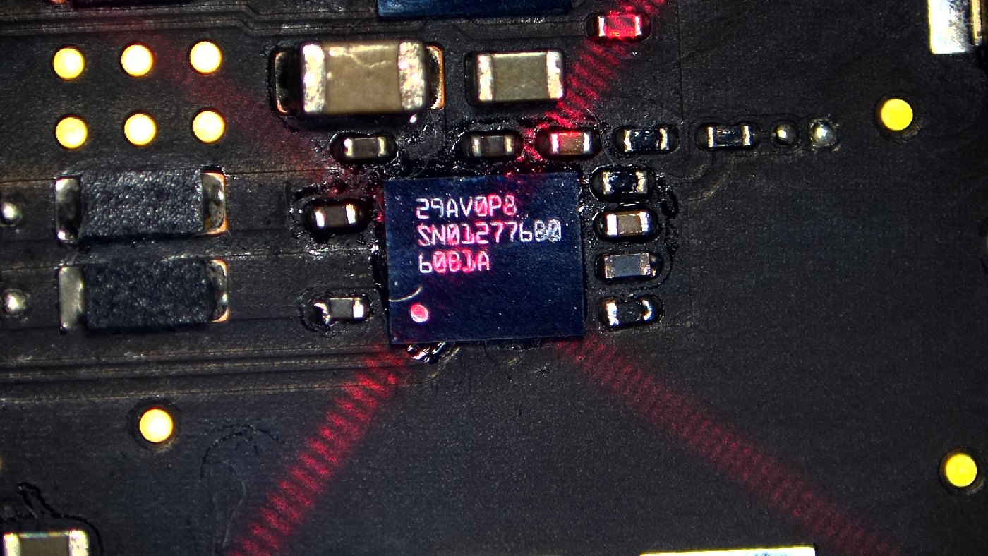
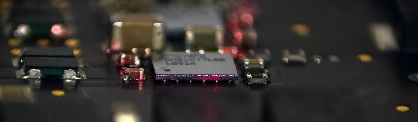
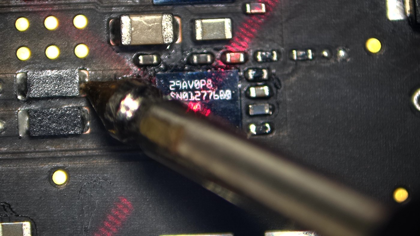
- CR708 now: 0.461 V in diode mode, steady. No short.
- Charger: 20 V, the Mac pulls 3.28 A = 64.5 W from a 65 W charger. It boots, and everything else works.
Step 6 – the next day: right speaker distorts. New amp, or the speaker?
On the test run the right side distorted while playing, and the distortion stopped when a fingertip touched the woofer. That points at the speaker itself, but UR700 (amp D) drives exactly that woofer (right connector JR850, pins 1–2). So before blaming the speaker, we proved the new amp.
Meter first (speaker unplugged, power off):
- Coil resistance: right woofer 1 = 3.78 Ω, right woofer 2 = 3.93 Ω. That looks low, but the left woofer 1 reads 3.82 Ω too, so the woofer-1 position just reads a little lower. That’s not a fault.
- Diode mode on the board side of both connectors (red probe on ground): the amp outputs read 0.463–0.471 V on every pin, left and right. The new amp D reads the same as its neighbours.
Then the scope while music plays. Probe on the JR850 pins (board side), with the untouched amp E (pins 3–4) as the reference.
Scope settings: 10X probe, DC, 2 V/div with −7 V offset (so 0 V sits near the bottom), 2 ms/div, peak detect.
How to read these pictures:
- A class-D amp switches its outputs on and off a few hundred thousand times a second. At 2 ms/div you can’t see single pulses. Peak detect paints the band from the lowest to the highest point, so the switching shows up as solid yellow blocks.
- This amp runs from two supplies (schematic page 121): PVDD = PPBUS (about 12 V) for loud passages and VBAT = PP3V8_AON (3.8 V) for quiet ones. That’s why there are tall blocks and short blocks. They are both normal.
- Black gaps = that output resting at 0 V for a moment. The reference amp does the same.
- The slight curve on the tops is PPBUS dipping a little under load. Amp E shows it too.
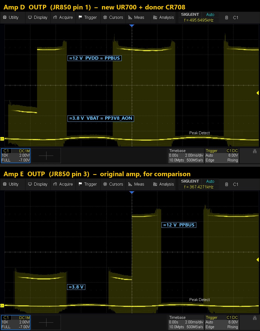
What a bad amp or a bad bootstrap capacitor would look like: the high side needs CR708 / CR709 to switch fully on. With a weak or wrong capacitor, the tall blocks fall short of the 12 V rail, sag, or drop out. Here the tops are flat at the full rail, same as amp E. So the donor CR708 works.
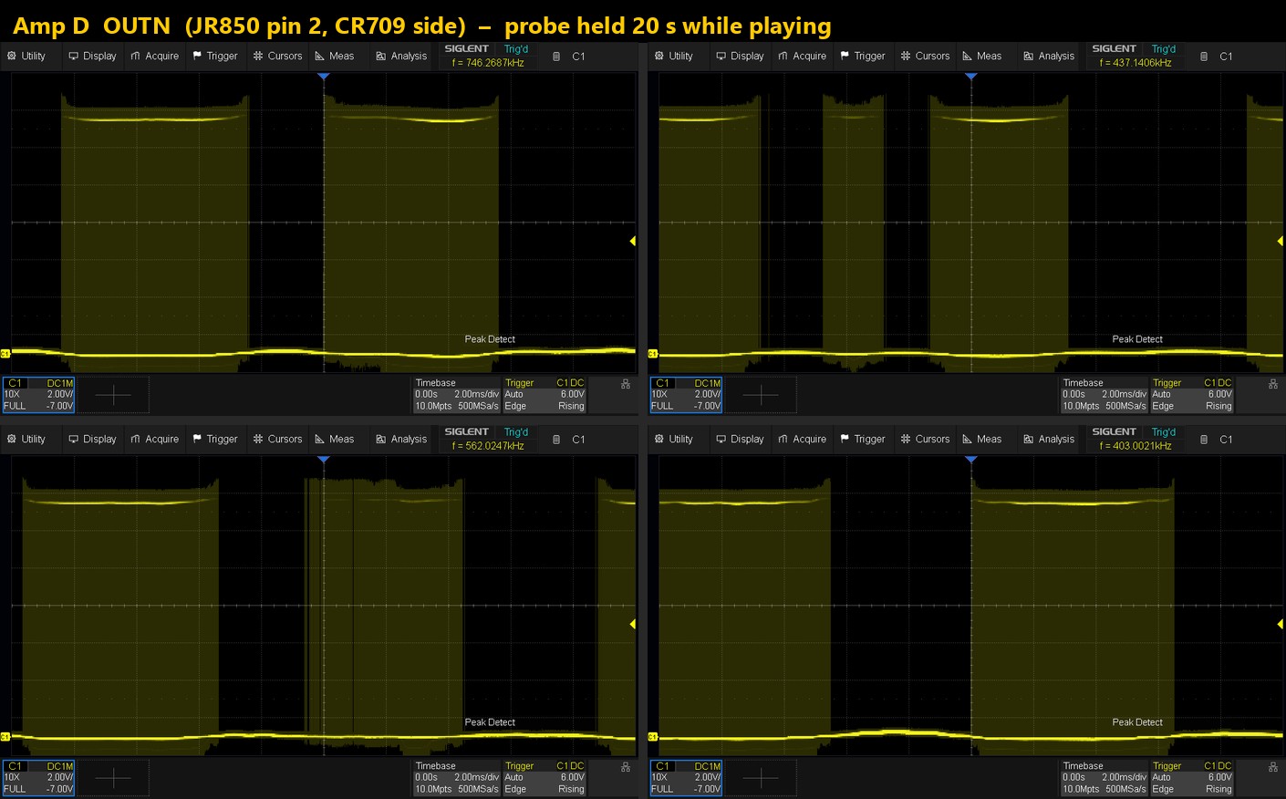
The other half of amp D (pin 2, bootstrap CR709) first read “flat 0 V” on some passes. That made the amp look half dead, but it wasn’t. The probe tip was slipping onto the ground pin next to it. Holding the probe on pin 2 alone for 20 seconds showed it switching the whole time:
Last check: does macOS see the new amp? The scope proves the amp switches power, but these amps are set up by macOS over I²C: gain, mode and protection are all written over the bus. A new chip that doesn’t answer on I²C, or that answers with errors, could still play badly. So we read the Mac’s own records in Terminal:
ioreg -rlw0 -c AppleSN012776Amp
log show --last 30m --style compact --predicate 'senderImagePath CONTAINS[c] "SN012776"'
- ioreg (the hardware list): macOS lists all six amps (
audio-control,sn012776× 6), and the amp driver AppleSN012776Amp is “registered, matched, active”. It sits on an I²C device and is powered on. The driver only gets that far after the chips have answered on the bus. - log show (the driver’s own messages, run right after playing music): empty. That means no errors, no I²C failures and no timeouts in 30 minutes.

Tips: paste each command as one single line, because a line break gives a grep “repetition-operator” error. To keep nothing on the customer’s Mac, add > /Volumes/<USB stick>/amp.txt and read the file on your bench PC. On other Macs, put your own amp’s part number in place of SN012776.
Verdict:
- Power side: amp D switches the full 12 V rail on both halves, the same as the original amp E.
- Control side: macOS finds the new amp over I²C, the driver is active and the log is clean.
The new amp is fine. The distortion is the right speaker module itself (woofer 1, mechanical: it stops when touched), so the fix is a new right speaker module.
Status: a new right speaker module is on order, ordered only after the scope and the macOS log had cleared the amp. I’ll post the result here once it’s fitted.
| Measurement | Before | After |
|---|---|---|
| PPBUS to ground, diode mode | 0.080 V (short) | short gone |
| USB-C charger | 5 V only | 20 V, 3.28 A, 64.5 W |
| CR708, diode mode | 0 (through the dead amp) | 0.461 V |
| Boot | dead | boots, all working |
| Amp D on the scope (pins 1 + 2) | – | full 12 V blocks, same as amp E |
| macOS amp driver (I²C) | – | 6 amps found, driver active, log empty |
| Right speaker distortion | – | speaker module (mechanical), not the amp |
Lessons
- “Stuck at 5 V” on a USB-C MacBook = check PPBUS for a short first. The charger and the port are usually fine.
- Speaker amps sit straight on PPBUS on these boards. One shorted amp kills the whole Mac, and there are six of them: UR600 / UR630 / UR660 (supply PPBUS_AON_SPKRAMP_ABC) and UR700 / UR730 / UR760 (PPBUS_AON_SPKRAMP_DEF). Check all six when PPBUS is shorted.
- A part that reads 0 next to a dead chip may only be reading the chip. Look at the schematic: if one side of it connects only to that chip, take the chip off and measure again.
- Test before you fit the new chip. The Mac runs without one speaker amp, so you know the board is otherwise healthy.
- Donor capacitors: same value AND voltage rating AND size.
- Distortion after an amp swap? Check both sides of the amp before blaming it: the scope for the power side (same blocks as its neighbour), and macOS
ioreg+log showfor the I²C side (driver active, no errors). Both clean means the amp is fine, so look at the speaker. - Probing tiny connector pins by hand: hold ONE pin for 20 seconds instead of sweeping across them. A “dead flat” reading is often just the tip slipping onto ground.
Was this your fault too? Post your readings below — and if it fixed it, mark the solution so the next person finds it.